The holidays are finally behind us, along with large, complex dinners and family gatherings. Between Thanksgiving, Christmas, and other holidays, many of us played host and were expected to present a meticulously prepared, extravagant spread for our guests to enjoy.
https://www.icqconsultants.com/wp-content/uploads/2023/01/icq-ellab-logo-300x81.png00Ashley Farleyhttps://www.icqconsultants.com/wp-content/uploads/2023/01/icq-ellab-logo-300x81.pngAshley Farley2020-01-08 11:08:022020-03-05 17:28:42Process Qualification of a Holiday Dinner
There is a current, popular trend called the “Konmari” Method created by Marie Kondo, which basically teaches you how to organize your possessions and life around you. This method, when put into practice, is designed to organize a person while keeping what is important and valuable and eliminating that of what is not. Overall, the message behind the method is about one key word – “Organization”.
ICQ Consultants, Michael Gatta and Peter Broomes will be attending tonight’s PDA New England Dinner Meeting & Berkshire Facility Tour. Please make sure to stop and say hello to them if you are there! The link below will provide the events agenda and description.
Biological indicators (BIs), as defined by ANSI/AAMI and ISO, are test systems containing viable microorganisms providing a defined resistance to a specific sterilization process. A biological indicator provides information on whether necessary conditions were met to kill a specified number of microorganisms for a given sterilization process, providing a level of confidence in the process. Endospores, or bacterial spores, are the microorganisms primarily used in BIs. These microorganisms are considered some of the toughest ones to kill. Additionally, bacterial spores are chosen for a specific sterilization process based on their known resistance to that process. For example, Geobacillus stearothermophilus spores demonstrate a high resistance towards steam and vaporized hydrogen peroxide and are therefore used in BIs that monitor these sterilization processes.
Biological indicators, depending on the specific type, can be used for various sterilization processes using steam, hydrogen peroxide gas, ethylene oxide and more. Several factors such as operator experience, load preparation and sterilizer condition can impact the sterilization cycle. BIs provide a direct measure of the lethality of the process and so the use of BIs to routinely monitor sterilizers provides assurance in the efficacy of the sterilization process. BIs are typically used within process challenge devices (PCD) that are designed to represent the most challenging products routinely processed. A passing result for the BI within this defined challenge demonstrates that the sterilizer is effective in killing many highly resistant bacterial spores, providing users with a level of assurance in their sterilization process.
Fastening BIs – Pitfalls and Tips
There are many ways to fasten BIs to your thermocouples, depending upon your specific activity. For example, utilization of BIs can vary from creating new loads for an autoclave or for a steam-in-place for a Bioreactor and transfer lines. It also depends on what type of materials are available (tie wraps, zip ties, autoclave tape, screens, etc.). The main idea here is to secure the BI while still allowing steam penetration. In an autoclave you have virtually no chance to overly damage/lose BIs because they are usually in tubing, autoclave bags, assemblies, etc. versus a steaming process in a transfer line. In which case, the steam and condensate flow in the lines can damage your wet BIs and also potentially damage your BI fastener causing you to lose them in the lines. For example, fastening a BI with the improper tie wraps could melt the tie wraps to the BIs and piping.
Practical Methodology
When wrapping the BIs for an autoclave, fold the BI around the thermocouple (towards the tip of the TC) by folding the BI so it resembles a mini-burrito. I have used autoclave tape on the BI edges to hold it to the TC and have also used tie-wraps. Either way, ensure the tape or tie wraps aren’t too tight (twist tie wrap a few times) to rip the envelope of the BI. Then place the BI with the TC into your load items.
When fastening the BIs for tanks/process lines, place the TC in the BI, fold it like a burrito, and then fold it in half. Take the tie wrap (approximately a foot long) and twist it around the BI starting at the top. With the remaining length of the tie wrap, twist it together so it secures the BI from moving. Since this one is a bit harder to visualize, refer below for a picture. It reminds me of a bottle rocket. Then you can either attach it to the TC or place it in the piping beside the TC ensuring an inch or two is secured by the clamp. This prevents the movement of the BI.
In Closing…..
Like many processes, there are multiple ways to get the job done. If this blog saves even one BI and an Engineering/Validation person’s resultant frustration, then it was all worth it!
Lack of experience with project scheduling by project team members is one of the biggest frustrations that a project manager/project scheduler faces. Projects in a matrix organization are often staffed with team members who are not familiar with project schedules. The team members provide input on tasks that they will need to perform to complete the project, but many times don’t include the pre-requisites for completing the tasks. Hopefully, after reading this blog, you might be able to contribute to a more accurate schedule.
Let’s Get to it!
We will work on a project where Equipment X is purchased and qualified for use. First thing, we need to do is identify all tasks involved in making toast and an estimate of how long they might take.
Now we put tasks in the order in which they need to be completed. We start out by purchasing the equipment. Many times in the biotech industry, the equipment has a long lead time because the equipment is not off the shelf and the manufacturer has to build it. Then a field acceptance test may need to be performed at the manufacture’s site to ensure that the equipment is working as expected before it is shipped to the site. Finally, it gets shipped to the site and is installed.
All those tasks were completed serially (one after another). In a project schedule, that is a finish to start (FS) relationship. When one task finishes, the next one can start. The task that finishes is called the predecessor and the one that is starting is the successor. The predecessor to “Installation” is “Delivery to site”.
Once the equipment is installed, the qualification activities can begin. First, the equipment start up and site acceptance testing. While this task is being completed, the commission protocol could be drafted in parallel. If the Subject Matter Expert forget to tell the project scheduler that these tasks can be completed in parallel, the project scheduler may assume that they need to be completed serially. The incorrect assumption would have resulted in a schedule that is inaccurately showing as taking two weeks longer, because the commissioning protocol would not have been drafted until the Startup and Site Acceptance Testing were completed. The schedule can easily be corrected for small issues such as this as long as the information is communicated to the scheduler.
In this example, the PQ execution start requires the IOQ Report to be completed and the PQ protocol to be completed. Let’s assume that Equipment X is a single use bioreactor that requires some single use bags for the PQ execution. If the project scheduler is not told that bags are needed and are a long lead time, the schedule will not have a task in there to remind them to purchase bags for the PQ. A lot of the times that there are delays with projects, it is due to small issues such as this, where the schedule is not capturing all the tasks and dependencies (ties between the different tasks).
In Closing….
To make your life and the project scheduler’s life easier and to be able to have a more accurate schedule, do the following:
Identify all the tasks that need to be completed for your part of the project
Estimate how long you think it might take to complete those tasks
Communicate this information to project schedule along with information such as Task A, B, and C need to be completed for D can start and A, B, and C can be completed in parallel.
When you get a copy of the schedule and you see something that doesn’t make sense, talk to the scheduler.
It may take a few iterations to come up with a schedule that has enough detail to ensure that project will not be derailed, so again, communication is necessary.
If you want don’t understand something about how the schedule has been setup, ask the project scheduler. Most of them will be more than happy to explain.
Related Terminology and Great Links
Activity: A task or process to be accomplished in a set period of time as part of working toward a larger project goal. An Activity can be assigned to a resource(s) and have an associated cost. Activities are ordered with logic links.
Activity Relationship: An ordered link between 2 activities representing the order of execution.
The 4 relationship types are:
FS – Finish to Start
SS – Start to Start
FF – Finish to Finish
SF – Start to Finish
Critical Path: A project’s critical path is the sequence of network activities which add up to the longest overall duration. This determines the shortest time possible to complete the project.
Float: Float is the amount of time that an activity in a project network can be delayed without causing a delay to: subsequent tasks (free float) or the project completion date (total float).
Gantt Chart: A time-based activity chart in which a series of horizontal lines shows the amount of work done or production completed in certain periods of time in relation to the amount planned for those periods. (example is shown above)
Predecessor(s): A predecessor activity is an activity that determines the start date or finish date of a following activity based on a logical relationship.
The Work Breakdown Structure (WBS): WBS is a hierarchical and incremental decomposition of the project into phases, deliverables and work packages. It is a tree structure, which shows a subdivision of effort required to achieve an objective; for example a program, project, and contract.
https://www.icqconsultants.com/wp-content/uploads/2023/01/icq-ellab-logo-300x81.png00Ashley Farleyhttps://www.icqconsultants.com/wp-content/uploads/2023/01/icq-ellab-logo-300x81.pngAshley Farley2019-10-04 18:40:182020-03-04 00:31:05Project Schedules: How to Help Yourself and the Project Scheduler
Ever since I was a child, I have loved to build. Like many kids of my generation, I grew up playing with Legos, Tinker Toys and Erector Sets. These objects would fill my days, providing hours of entertainment. The best part about these toys was their versatility. You could build things and disassemble them to make new things over and over again. Of all the toys, I loved Legos the most. Perhaps that is why I love the concept of modular manufacturing in BioPharm.
When I started out in BioPharm over 20 years ago, I came in at a time when companies were spending more and more on large facilities. I was making vaccines in bioreactors and the rooms and buildings to hold them were getting larger and larger. Older facilities in which I worked were forced to retrofit rooms and entire buildings to fit their process. Other sites with room and money for expansion built new large manufacturing buildings. These newer larger facilities focused on large stainless steel bioreactors up to 10-25k liters became the norm for the industry.
Nearly 10 years later, I was an engineer on a start-up project for a large biotech company that included four levels of process equipment for upstream and downstream processes in a new manufacturing building with additional support buildings and renovations to older buildings at a cost of nearly $1B. Facilities like these required high initial capital investment and large overhead. The challenge with this type of design is that these facilities have large capacities but a limited amount of flexibility. Dramatic increases in product titers and yield coupled with the ever-expanding role and incorporation of single-use systems has offered more flexible approaches to manufacturing and has started a bit of a revolution in so called flexible facilities. These flexible facilities offer a more flexible approach to manufacturing.
Some flexible options
Many of the new facilities and renovated older facilities now use modular systems. There are several types of modular systems with a variety of physical configurations:
modular room enclosure systems (such as from Daldrop, AES, or Plascore);
modular room enclosure systems with utility systems (such as from G-CON Manufacturing or SmartFit Modular);
building modules with utility systems (such as from Pharmadule/Morimatsu);
or building modules with process systems (such as GE Healthcare Life Sciences’ KUBio FlexFactory platform) (1).
A full module typically is fashioned with its own mechanical, electrical, HVAC ductwork, high-efficiency particulate air filters, and plumbing systems and process equipment is usually already part of the module (2). In addition, closed modular systems are said to reduce required manufacturing area, HVAC requirements, chilled water and steam demands associated with cleaning, construction and start-up times, and potentially, cost of goods (3). Use of modularization is growing because it meets the industry needs for reduced cost, accelerated construction schedules, and quality construction. Modularization allows parallel paths for construction activities, such as process-piping and equipment construction, in parallel with some of the activities that take place to erect the building shell.
Validation considerations
I am truly intrigued by the impact that these modular facilities will have on validation activities. Many facilities make use of a pre-existing building shell and have the manufacturing pods/modules delivered to the site. Units such as the G-CON PODs typically incorporate the mechanical and electrical systems required to operate the POD, including the air handler units, exhaust fans, fire suppression, power and control systems, and waste handling systems. Utility connection points to the POD are typically located on the external wall of the POD mechanical area, allowing for easy integration with the facility utility systems.
Because much, if not all, of the HVAC and utilities come with the modular units, documentation and validation of these facilities are more simplified and streamlined. And anyone who has climbed around in dark mezzanine’s between ductwork looking for tags and labels and tracing utilities and piping while holding a flashlight and a validation protocol will welcome such a change.
Real world Legos…
Facility design requirements in Biopharm are changing, and modular facilities are becoming a reality. In the near future, facilities will be able to change their facility design to meet changing business needs as easily as a child can disassemble a Lego structure and build a new one. As more companies offer modular manufacturing, the more we will see things standardized across the industry. And industry standardization typically means better guidance, clarity of regulations, and ease of validation.
Written By: Greg Steele, Senior Consultant
Hernandez, “Modular Manufacturing Platforms for Biologics,” BioPharm International28 (5) 2015.
Gilroy and G. Martini, Pharmaceut. Proc. 27, pp. 22-23 (2012).
L. Nelson, “Approaches for Flexible Manufacturing Facilities in Vaccine Production” supplement to BioPharm Internat. 24, pp. s22-28 (2011).
Join our network, follow us, like us and share this on LinkedIn, Twitter and Facebook so you can see other new and exciting news and discussions being posted by ICQ Consultants. Or visit our website and get and in depth view of what we are all about: http://icqconsultants.com.
https://www.icqconsultants.com/wp-content/uploads/2023/01/icq-ellab-logo-300x81.png00Ashley Farleyhttps://www.icqconsultants.com/wp-content/uploads/2023/01/icq-ellab-logo-300x81.pngAshley Farley2019-08-29 18:39:122020-03-04 00:31:05Mods and Pods in BioPharm
Have you ever completed the temperature mapping / qualification testing for a walk-in refrigerator or freezer and felt good about the data? That is until someone asked you to relate what the numbers mean in relation to the system and what was happening inside the unit. You knew the results met the acceptance criteria, but maybe weren’t so sure how they related to system performance.
Cooling and Heating…How Does It Work?
All Temperature Controlled Units (TCUs) have five main components:
Microprocessor
TCU Engine
Compressor
Condenser
Evaporator
An area containing all of the main components listed above with the exception of the evaporator is located outside the controlled environment space (e.g. outside the cold room).
The compressor pumps refrigerant through the temperature-controlled system. It works with the engine to increase pressure triggering the refrigerant to change phase from a gas to a liquid. Due to the phase change the refrigerant will heat up during compression. The liquid refrigerant is then pumped to the condenser. The condenser removes the heat absorbed by the refrigerant from the compressor and temperature-controlled area. As the heat is being absorbed the refrigerant approaches thermal equilibration with the ambient air outside the controlled environment space. Once the refrigerant has been cooled to a liquid it flows through an expansion valve into the evaporator. The evaporator then transfers heat out of or into the controlled environment space to control the area temperature. The refrigerant changes back to a gas as it absorbs heat. The heated refrigerant then flows back through the compressor and the cycle starts over. As you might have guessed, the heating process of a refrigeration unit is usually the opposite of the cooling process. The evaporator becomes the condenser and vice versa.
What about the defrost cycle you ask?
The defrost cycle is used to prevent the system from forming ice. When and how often the defrost cycle is used is based on measurements of the coils temperature at given time intervals. A timer closes the circuit which then allows air to flow to a temperature sensor. If the temperature falls within the temperature range that would allow the formation of ice, the unit will start a defrost cycle. Typically, an electric heater is used to defrost the evaporator. Obstruction of airflow due to evaporator icing may also trigger the defrost cycle to begin.
Parting Thoughts
An actively temperature-controlled system is designed to maintain the air temperature within a defined space, thereby insulating the stored goods from the effects of outside conditions. To achieve this, the air inside the system must be able to flow throughout the area being controlled. If your data is meeting acceptance criteria then great, everything is probably fine. But if it’s not then your issue probably lies with a critical design parameter such as: sufficient capacity for heat exchange, proper airflow, thermal integrity, and air velocity. All of these are as crucial to a temperature control system, including monitors and alarms, as they are to the refrigeration process.
Written By: Nathan Roberge, Consultant III
Reference:
Active Temperature-Controlled Systems: PDA Technical Report No. 64; 2013
https://www.icqconsultants.com/wp-content/uploads/2023/01/icq-ellab-logo-300x81.png00Ashley Farleyhttps://www.icqconsultants.com/wp-content/uploads/2023/01/icq-ellab-logo-300x81.pngAshley Farley2019-06-28 18:38:212020-03-04 00:31:05Temperature Controlled Systems: Refrigerators and Freezers
We may request cookies to be set on your device. We use cookies to let us know when you visit our websites, how you interact with us, to enrich your user experience, and to customize your relationship with our website.
Click on the different category headings to find out more. You can also change some of your preferences. Note that blocking some types of cookies may impact your experience on our websites and the services we are able to offer.
Essential Website Cookies
These cookies are strictly necessary to provide you with services available through our website and to use some of its features.
Because these cookies are strictly necessary to deliver the website, refusing them will have impact how our site functions. You always can block or delete cookies by changing your browser settings and force blocking all cookies on this website. But this will always prompt you to accept/refuse cookies when revisiting our site.
We fully respect if you want to refuse cookies but to avoid asking you again and again kindly allow us to store a cookie for that. You are free to opt out any time or opt in for other cookies to get a better experience. If you refuse cookies we will remove all set cookies in our domain.
We provide you with a list of stored cookies on your computer in our domain so you can check what we stored. Due to security reasons we are not able to show or modify cookies from other domains. You can check these in your browser security settings.
Google Analytics Cookies
These cookies collect information that is used either in aggregate form to help us understand how our website is being used or how effective our marketing campaigns are, or to help us customize our website and application for you in order to enhance your experience.
If you do not want that we track your visit to our site you can disable tracking in your browser here:
Other external services
We also use different external services like Google Webfonts, Google Maps, and external Video providers. Since these providers may collect personal data like your IP address we allow you to block them here. Please be aware that this might heavily reduce the functionality and appearance of our site. Changes will take effect once you reload the page.
Google Webfont Settings:
Google Map Settings:
Google reCaptcha Settings:
Vimeo and Youtube video embeds:
Other cookies
The following cookies are also needed - You can choose if you want to allow them:
Privacy Policy
You can read about our cookies and privacy settings in detail on our Privacy Policy Page.
 ICQ Consultants, Michael Gatta and Peter Broomes will be attending tonight’s PDA New England Dinner Meeting & Berkshire Facility Tour. Please make sure to stop and say hello to them if you are there! The link below will provide the events agenda and description.
 indicators (BIs), as defined by ANSI/AAMI and ISO, are test systems containing viable microorganisms providing a defined resistance to a specific sterilization process. A biological indicator provides information on whether necessary conditions were met to kill a specified number of microorganisms for a given sterilization process, providing a level of confidence in the process. Endospores, or bacterial spores, are the microorganisms primarily used in BIs. These microorganisms are considered some of the toughest ones to kill. Additionally, bacterial spores are chosen for a specific sterilization process based on their known resistance to that process. For example, Geobacillus stearothermophilus spores demonstrate a high resistance towards steam and vaporized hydrogen peroxide and are therefore used in BIs that monitor these sterilization processes.


 In this example, the PQ execution start requires the IOQ Report to be completed and the PQ protocol to be completed. Let’s assume that Equipment X is a single use bioreactor that requires some single use bags for the PQ execution. If the project scheduler is not told that bags are needed and are a long lead time, the schedule will not have a task in there to remind them to purchase bags for the PQ. A lot of the times that there are delays with projects, it is due to small issues such as this, where the schedule is not capturing all the tasks and dependencies (ties between the different tasks).
 I am truly intrigued by the impact that these modular facilities will have on validation activities. Many facilities make use of a pre-existing building shell and have the manufacturing pods/modules delivered to the site. Units such as the G-CON PODs typically incorporate the mechanical and electrical systems required to operate the POD, including the air handler units, exhaust fans, fire suppression, power and control systems, and waste handling systems. Utility connection points to the POD are typically located on the external wall of the POD mechanical area, allowing for easy integration with the facility utility systems.
 Facility design requirements in Biopharm are changing, and modular facilities are becoming a reality. In the near future, facilities will be able to change their facility design to meet changing business needs as easily as a child can disassemble a Lego structure and build a new one. As more companies offer modular manufacturing, the more we will see things standardized across the industry. And industry standardization typically means better guidance, clarity of regulations, and ease of validation.
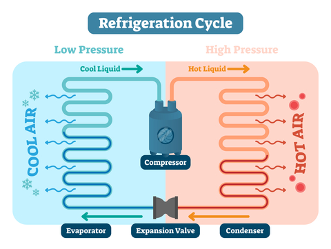
 An actively temperature-controlled system is designed to maintain the air temperature within a defined space, thereby insulating the stored goods from the effects of outside conditions. To achieve this, the air inside the system must be able to flow throughout the area being controlled. If your data is meeting acceptance criteria then great, everything is probably fine. But if it’s not then your issue probably lies with a critical design parameter such as: sufficient capacity for heat exchange, proper airflow, thermal integrity, and air velocity. All of these are as crucial to a temperature control system, including monitors and alarms, as they are to the refrigeration process.